Properly installing a disc stack centrifuge eliminates several operational issues faced by users. This guide discusses the various aspects of the storage and proper installation of disc stack centrifuges.
Though this guide refers to Alfa Laval disc centrifuges, the recommendations are also applicable to disc stack centrifuges from other manufacturers.
Storage Before Installation
The centrifuge system is often delivered to the customer site before the plant is ready to utilize it. In such cases, the proper storage of the centrifuge is necessary. We recommend the following steps for storage before installation.
Location
The system should be stored indoors to protect from rain, dust, and other contaminants. The user may store the equipment outdoor if it is in a weatherproof crate with a vapor barrier lining.
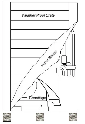
The centrifuge storage should be in a well-ventilated area with the temperature maintained above the local dew point temperature in humid conditions.
Storage Temperature
The ideal storage temperature is between 40 F and not exceeding 140 F. Also, never store the centrifuge in locations where the temperature can go below freezing.
Physical Installation
The physical installation refers to placing the centrifuge system within the processing plant. This aspect of the installation needs to be carefully considered based on the key points mentioned below.
Placement
The centrifuge system placement in the plant should allow for easy access for the initial installation and the centrifuge extraction for future service or replacement. Therefore a clear pathway to the centrifuge skid should be provisioned during installation.
Clearances
The service of centrifuge components requires adequate space around the centrifuge to enable the removal and reinstallation of such components. In this section, we highlight the critical clearances that need consideration.
Overhead
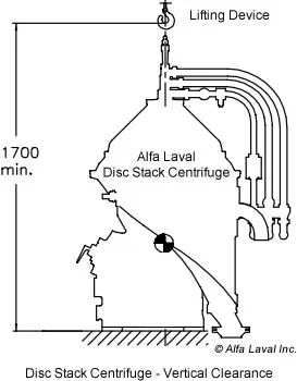
The disc stack centrifuge has a vertical orientation. The centrifuge bowl extraction occurs through the top of the centrifuge. A mechanical assist device such as a hoist or a crane is the preferred extraction mode.
Therefore, overhead clearance is critical for the regular service of a disc stack centrifuge. The centrifuge manual specifies the required clearance for specific centrifuge models.
Side Access
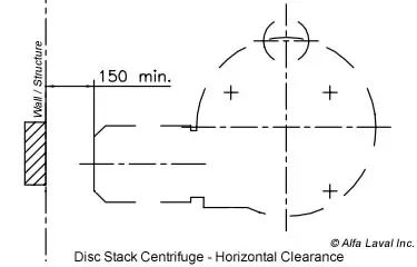
The main drive motor on a disc stack centrifuge has a horizontal orientation. Therefore adequate clearance behind the motor is essential for the extraction for the repair or replacement of the centrifuge motor. See reference horizontal clearance diagram above.
Foundation & Anchoring
All industrial centrifuges have heavy bowls that rotate at high operating speeds. This rotation causes the centrifuge to vibrate. A rigid foundation for the centrifuge system is therefore highly recommended to negate the effects of this vibration.
Ideally, it is best to anchor the centrifuge base to a level concrete slab for maximum stability.
Elevated Platform Installation
In some cases, the centrifuge installation is on elevated platforms. This type of installation could allow the centrifuge effluent to gravity feed downstream equipment located below the centrifuge. As mentioned above, the centrifuge's inherent vibration should be carefully observed during elevated platform installation.
Platform Design
A qualified structural engineer needs to design the centrifuge elevation platform. The static and dynamic loads of the centrifuge are vital inputs in the design calculations. The designer should also consider the platform's resonant frequency with the centrifuge's natural frequencies.
Platforms designed without proper considerations mentioned above can lead to catastrophic structural failure and personal injury.
Service Access Provision (Catwalk)
The centrifuge operator requires level access to service the bowl and disc stack during maintenance. A platform-level catwalk is ideal for ease of access during service. The provision for such a catwalk is highly recommended.
Indoor and Outdoor Installations
Indoor Installation
Most centrifuge installations are indoors or within some structural enclosure, such as a building. These types of climate-controlled locations are ideal for reliable and long-term centrifuge performance.
The constant temperature within buildings helps with the trouble-free operation of the centrifuge. This reliability is mainly because wide temperature fluctuations can the electrical and mechanical components to malfunction.
Indoor installations also protect the centrifuge system from natural elements such as rain, snow, dust, etc.
Outdoor Installation
Under certain conditions, it is not feasible to have an indoor installation for the centrifuge. In such cases, an outdoor installation of the centrifuge is permissible as long as some additional steps are taken to protect the centrifuge from the elements.

At a minimum, an overhead canopy or roof over the centrifuge is highly recommended as shown in the image above.
Other disc-centrifuge articles of interest......
Centrifuge Location In Relation To Accessory Tanks
A disc stack centrifuge typically has a supply or feed tank that contains the contaminated fluid, and It also has a clean (separated) fluid receptacle or discharge tank. The centrifuge sucks the dirty fluid from the feed tank and discharges the clean fluid to the discharge tank. The following are points to consider for the location of these tanks.
Supply (Feed) Tank & Pump
The supply tank should be near the centrifuge system, and the supply pump should be at or near the tank's base. This placement avoids too much suction on the feed liquid and positive pressure in the supply pipe.
Locating the pump near the supply tank also keeps the pump suction flooded to prime the pump and prevent air pockets in the supply pipe.
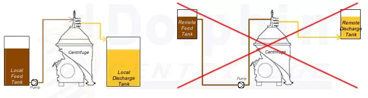
Processed (Clean) Fluid Tank
The clean fluid or discharge tank's location is essential, and the ideal location of the discharge tank is close to the centrifuge system. A far-off location of the discharge tank can cause back pressure on the centrifuge outlet.
Any back pressure exerted on the clean fluid outlet of the centrifuge causes a flow restriction. It can also affect the liquid-liquid interface's stability within the centrifuge bowl, which affects centrifuge efficiency.
Sludge Tank
The self-cleaning disc stack centrifuge ejects the sludge automatically through its base downward. Dolphin Centrifuge systems integrate a sludge tank into the skid base, eliminating the need for a separate tank or skid elevation.
If a sludge tank needs to be provided, the tank's ideal position is directly below the centrifuge skid. The sludge can fall directly into the tank in this configuration.
Location of Electrical Control System
One of the critical components of the centrifuge system is the electrical control system. This control panel houses various electronic parts that are sensitive to heat and other environmental factors. The following sections discuss the proper location of the centrifuge electrical control system for reliable system operation.
Ambient Temperature
The electronic control system components are susceptible to high temperatures. Therefore, it is essential to locate centrifuge control panels in temperatures below 140 F. System malfunction and shutdown can occur due to higher temperatures exposure to control systems.
Proximity to Heat Source
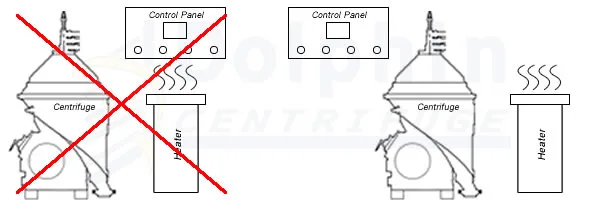
As mentioned earlier, the centrifuge control panel should not be close to any external heat source, such as electric heaters. The indirect heat from these sources can overheat the control system causing system malfunction.
Placement
Though most control system enclosures have protection from water and fluid ingress, it is advisable not to locate control panels under process or water pipes. Inadvertent leaks or condensation on the control system boxes are known to cause operational issues.
Piping
Proper design of process-related piping connecting to the centrifuge system is essential for trouble-free operation. In the following section, we have described the recommended piping methods for each type of pipe.
Process Fluid Pipe Size
The pipe selected for process fluid should be large enough to allow the process fluid to flow without restriction. Also, one should keep the number of bends to a minimum.
Heat Tracing and Pipe Insulation
In the case of viscous liquids, especially in colder climates, heat tracing & insulation of the process piping is desirable. Pipe insulation reduces heat loss during flow to and from the centrifuge. Heat tracing prevents blockages in the pipe when the system is not operating, and the viscous fluid in the pipe can potentially block the flow.
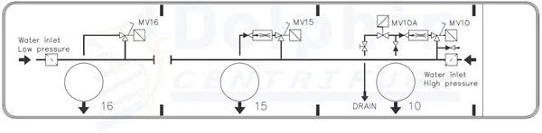
Operating Water Pipe
The operating water pipe feeds the water for the hydraulic operation of the bowl sludge ejection system. The operating water needs to be clean and free of dissolved solids. To prevent the pipe's rust, the operating water pipe material must be non-corrosive. Stainless steel, copper, or PVC are the recommended materials for operating water.
The centrifuge requires a minimum water flow to operate. The operating water pipe needs to be of the appropriate size to supply the volume of water needed. Depending on the size of the centrifuge, a water pipe with the correct diameter should be used.
Provisioning the operating water pipe to the centrifuge location is prudent before the installation. It is more laborious to route the operating water pipe to the install location once the centrifuge is installed.
Sludge Pipe
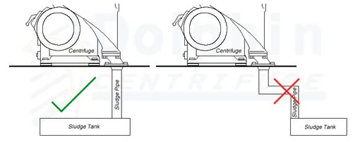
The sludge pipe conveys the separated sludge into the sludge tank. The centrifuge discharges the sludge accompanied by a pressure pulse. The sludge pipe must have a constant size (diameter) without any reducers or bends.
Also, one should always connect the sludge pipe to the top of the sludge tank. The sludge pipe should not immerse in the accumulated sludge. An immersed sludge pipe can recoil the sludge back into the centrifuge, causing operational issues.
Air Pipe (Tube)
Disc stack centrifuge systems with 3-way diverter valves and AODD sludge pumps require compressed air. The air supply pipe (tube) should have a minimum size for the air consumption flow rate of the AODD.
The air supply line should also have an air pressure regulator and a desiccant drier to prevent condensation from damaging the pumps and actuators.
Utilities
A disc-stack centrifuge uses the following utilities. It is advantageous to plan for these utilities before the centrifuge installation. One should pay proper attention to the utility lines' layout for ease of installation and centrifuge operation.
Power
Industrial centrifuge systems use a high-voltage power supply. In the US, 460 Volt, 3-Phase power supply is standard. Depending on the user's existing system, the provision of the correct power supply voltage is needed. Also, the current load of the complete system needs to be anticipated.
The current drawn by the centrifuge system will determine the power cable sizes and the local service disconnect.
The design and installation of the proper electrical utility supply will ease centrifuge startup.
Water
As previously stated, the operating water supply affects centrifuge performance and trouble-free operation. The operating water specifications are listed in the centrifuge operating manual specific to the centrifuge. One should design the operating water supply to the proper water pressure and flow specified.
Typically the installation of a water pressure reducer regulates the incoming water to the desired pressure. The flow rate of the water depends on the pipe size.
The provisioning of the water supply system close to the disc stack centrifuge is highly recommended. This setup eliminates long water hoses with potential pressure drops.
Finally, clean and potable water is essential for the self-cleaning disc stack centrifuge's reliable, long-term operation. Mineral deposits and sediment block the operation of the sludge discharge mechanism.
Compressed Air
The 3-way diverter valve used compressed air to divert the incoming fluid flow to the centrifuge or the recirculating line. The sludge pump (if included on the skid) also uses compressed air for its operation. The supply of dry, filtered air is key to the trouble-free operation of these devices.
Inert Gas
Explosion-proof centrifuge control panel enclosures use inert gas (nitrogen or argon) for purging. In some applications, the isolation of the product from ambient air (oxygen) is desirable. Inert gas blanketing is the preferred method for such product isolation.
A continuous supply of inert gas is essential for the safe operation of an explosion-proof centrifuge system.
Therefore, planning the inert gas supply line close to the centrifuge location is beneficial for ease of installation.
Water Drain
The operating water drains from the centrifuge frame during regular operation and usually is not contaminated. The discharge of the operating water from the disc centrifuge is under gravity. Therefore, a floor water drain in the vicinity of the centrifuge is required.
Venting
Sludge Tank Vent
Self-cleaning disc stack centrifuges eject the separated solids accompanied by a pressure pulse. The vent on the sludge tank allows this pressure surge to escape.
Depending on the fluid type, the vent may need to be connected to an external venting exhaust system.
Advance planning for the local vent for the sludge tank assists in an expedited centrifuge installation.
Centrifuge Casing Vent
Disc stack centrifuges process different fluids, some of which emit vapors and fumes. These fumes can be a safety hazard to the operators and the facility. Therefore, it is crucial to handle these vapors to be exhausted from the local area.
Centrifuge casing vents provide a discharge port for the vapors that accumulate within the centrifuge vessel or casing. A mild suction vent transfers these vapors away from the centrifuge to be exhausted safely.
An exhaust duct's provisioning to connect with the centrifuge casing vent is desirable when handling fluids that emit hazardous vapors.
Installation Area Vent
In some installations, such as crude oil de-sludging, the purged casing may emit trace light ends of the crude oil. This local dissipation can occur despite the centrifuge vessel purging. In such instances, the designer may consider a local overhead venting exhaust system.
These area vents look like an overhead canopy with an inverted funnel appearance. They serve to collect and exhaust the harmful vapors emitted by the centrifuge during operation.
Summary
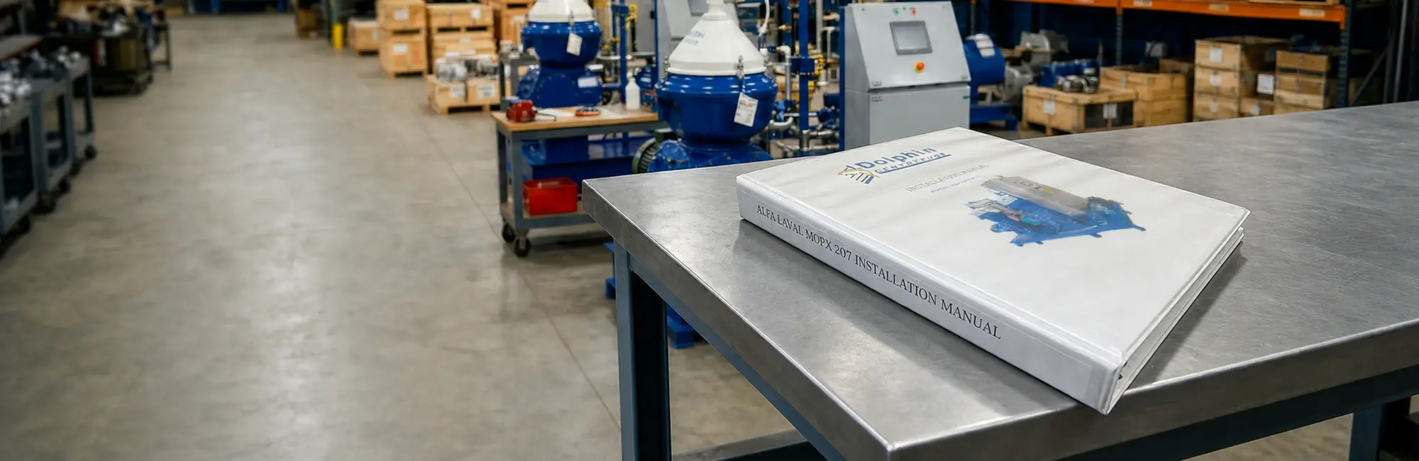
Disc stack centrifuge installation is an essential first step to ensure the long-term reliable operation of the centrifuge system. The centrifuge installation manual supplied with the centrifuge has specific details relevant to the centrifuge model.
The end-user centrifuge installation plan should consider these specifications to ensure ease of centrifuge startup and continued operation.