Disc stack centrifuge performance depends on several factors that are internal and external. Internal factors are those which are related to the centrifuge and the process fluid.
We will discuss the external factors here. You can also read our blog about internal factors that affect centrifuge efficiency.
Read our 101 Frequently Asked Questions about Disc Stack Centrifuges!
Ambient Temperature
The ambient temperature of the centrifuge location affects the performance of the centrifuge in a few ways. Colder environments are detrimental to centrifuge performance. This effect is exasperated if the process fluid is temperature-sensitive.
Physical Effects on Centrifuge Mechanics
Extreme ambient temperature affects the centrifuge in a few ways. One is the effect of temperature on the internal centrifuge lubrication.
The temperature of the operating water and clogging of the centrifuge passages by process fluid constituents are other possible effects.
Lubricating Oil Viscosity
In colder environments, the viscosity of the lubricating oil in the centrifuge gearbox increases. The viscous lube oil increases the resistance to the gear motion. As a result, the motor's current draw increases, which may also cause the motor to heat up.
The heat generated by the centrifuge operation gradually increases the lubricating oil's temperature and reduces the viscosity. With the lower lube oil viscosity, the motor current draw typically falls back into the normal operating range.
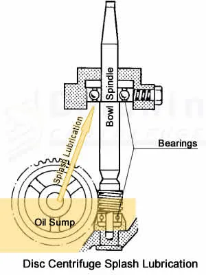
It is important to note that the centrifuge incorporates a splash lubrication system that relies on the lubricant's viscosity. The thicker lubricant in cold environments may affect the lubrication of the centrifuge bearings.
As mentioned above, the friction between the gears and other components generates heat in the gearbox. High ambient temperatures can overheat the lubricant, leading to the transmission components' premature failure, including the bearings and gears.
Operating Water Temperature
As explained in our articles on centrifuge operating water systems, the centrifuge's hydraulic mechanism requires the water to be in a fluid state. Sub-zero temperatures will freeze the operating water and prevent the centrifuge from working as intended. Therefore, the user should never operate the centrifuge in sub-zero ambient temperatures.
Cold operating water also has a cooling effect on the centrifuge bowl. If the process fluid is temperature-sensitive, the cold water will have a cooling effect on the process fluid. The cooling will increase the fluid's viscosity, adversely affecting the separation efficiency and centrifuge performance.
Gelling of Process Fluid Constituents
In some applications, the process fluid carries components that gel at lower temperatures. For example, in crude oil processing, paraffin is often present in crude oil. At lower temperatures, this paraffin becomes solid and sticks to narrow internal bowl passages. This accumulation of the paraffin causes a restriction of the fluid flow affecting the centrifuge performance.
It is necessary to remove these restrictions by flushing the bowl with hot water or a solvent in such applications. This extra step further affects centrifuge performance and uptime.
Other disc-centrifuge articles of interest
- Disc Centrifuge Backpressure - Comprehensive Guide
- 9 Steps to Selecting & Buying the Right Industrial Centrifuge
- Centrifuge RCF and RPM | Difference & RCF Calculation
- Disadvantages of a Disc-Stack Centrifuge | Illustrated Guide
- Difference Between Decanter & Disc Centrifuge | Technical Comparison
Type of Feed Tank
Industrial centrifuges perform optimally when the process fluid is homogeneous. This homogeneity means that the process fluid is consistent in the proportion of the contaminants. In other words, process fluid fed from an agitated tank is highly desirable.
Conversely, cone bottom or other types of settling tanks are not suitable as feed tanks for disc-stack centrifuges. The Cone bottom tank design is to collect the solids via gravity separation. So, if the process fluid comes to the disc-stack centrifuge from such a tank, it is likely that the initial fluid will carry large amounts of settled sludge.
This glut of solids will cause the disc-stack to get packed with solids and effectively render the centrifuge unable to process.
Ideally, a centrifuge feed tank should be a flat bottom tank with constant agitation. The agitation keeps the solids in suspension, avoiding the issue mentioned above.
Location of Feed Tank
Industrial centrifuge users often feed the centrifuge from a feed tank located outdoor. In colder climates, the outdoor location cools down the process fluid quickly. Again, this affects the centrifuge performance for temperature-sensitive fluids that become more viscous at lower temperatures.
We recommend an indoor local feed tank in the vicinity of the centrifuge. This tank uses less energy to keep warm and therefore increases the total process efficiency. The tank capacity should be adequate to supply the centrifuge with the required amount of fluid for the anticipated batch.
Location of Discharge Tank
The location and elevation of the discharge or clean fluid collection tank are crucial. A remotely located collection tank has a few disadvantages that affect centrifuge performance.
Centrifuge Back Pressure
Most disc-stack centrifuges discharge the clean fluid under pressure through an internal paring disc pump. Considerable pressure is required to transfer the processed fluid to a remote tank. This transfer-related pressure exerts back pressure on the centrifuge. Excessive back pressure affects the performance of the centrifuge.
Climate Effect on Discharge Piping
If the discharge tank location is outdoor, the colder climates' external temperature cools down the process fluid. This cooling increases the viscosity of oils, exerting pressure on the centrifuge.
Under such conditions, the insulation and heat tracing of the discharge piping is desirable.
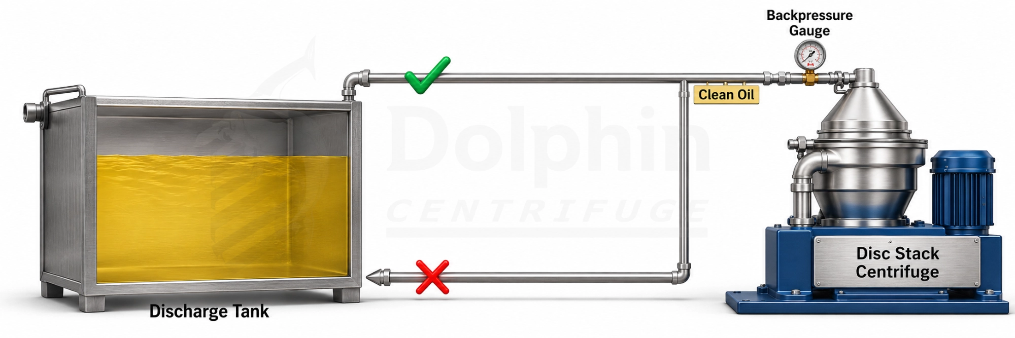
Discharge Tank Connection Location
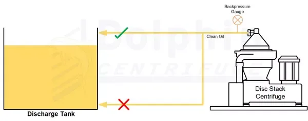
As previously explained, disc centrifuges work best under consistent operating conditions. The connection between the discharge pipe and the discharge tank is often overlooked.
Connecting the discharge pipe to the bottom of the collection tank is easy to install. However, this location is not desirable for centrifuge performance.
A discharge connection to the tank bottom will create pressure in the discharge pipe based on the tank's fluid level. With the changing fluid level, the backpressure in the discharge pipe will also change. Disc-centrifuge performance is affected by back pressure.
Therefore, a discharge pipe connected to the tank bottom is unsuitable for optimal centrifuge performance.
The centrifuge discharge pipe ideally connects to the top of the discharge tank. In this configuration, the pressure exerted by the fluid in the pipe remains constant and does not affect centrifuge operation.
Feed Tank Agitation
Homogenous process fluid ensures optimum centrifuge performance, as explained previously. The simplest way is to mix the process fluid through agitation. A supply tank fitted with an industrial agitator serves this purpose effectively.
A top-mounted paddle mixer rotating at a low RPM is ideal for keeping the solids in suspension.
Type of Feed Transfer Pump
We recommend positive displacement pumps for feeding disc-stack centrifuges. These types of pumps do not churn the liquid and thus avoid the creation of emulsions.
Ger pumps or progressive cavity pumps are best suited for feeding centrifuges.
Centrifugal pumps churn the fluid, possibly creating undesirable emulsions in certain types of oil-water mixes.
Air diaphragm pumps create pressure pulses in the feed liquid. This pulsation affects the liquid-liquid interface in the bowl affecting centrifuge performance. Therefore, air diaphragm pumps are also not recommended for disc centrifuges.
Sludge Tank
Alfa Laval disc-stack centrifuges discharge the sludge through the bottom of the frame. The sludge ejection is in a downward direction under gravity. The following factors related to the sludge collection tank affect centrifuge performance.
Venting
The high centrifugal force within the centrifuge bowl causes a pressure pulse to accompany the discharged sludge. Therefore, venting the sludge tank is crucial to allow this pressure to escape into the atmosphere.
A sealed sludge tank can cause the ejected sludge to deflect back into the centrifuge. The deflected sludge accumulates in the bowl operating cavity and interferes with the bowl opening mechanism affecting the centrifuge's performance.
In worst-case scenarios, the pressurized sludge can cause the sludge tank to explode, causing equipment damage and possible operator injury.
Location
The centrifuge ejects the sludge through the frame bottom downward. Therefore, the ideal sludge tank location is directly under the centrifuge.
Connection
Given that the ejected sludge comes out at significant velocity, it is best to avoid obstructions such as bends or size reductions in the sludge outlet chute. In other words, the sludge tank connection hose should be of uniform cross-section and in a vertical position.
by Sanjay Prabhu MSME
Engineering Manager, Dolphin Centrifuge