Disc centrifuge parts are the bowl, disc stack, spindle, paring disc, distributor, sliding piston, lock rings, seals, operating water parts, and related components used inside an industrial disc stack centrifuge. This glossary explains the uncommon names and functions of Alfa Laval disc centrifuge bowl parts so maintenance teams can identify parts correctly during repair, troubleshooting, and parts requests.
Synopsys
Disc centrifuges are a unique set of machinery that has its own parts and related vocabulary. There are specific terms used when referring to disc centrifuges, which are uncommon.
We have categorized these terms into two subcategories. The first section explains parts specific to disc centrifuges, and the second section explains terms unique to disc centrifuges.
This first section elaborates on the unique centrifuge parts common to Alfa Laval disc centrifuges. We describe the specific component's function and illustrate it within the exploded view of the assembly or a photograph. This explanation will help the reader understand the part in detail.
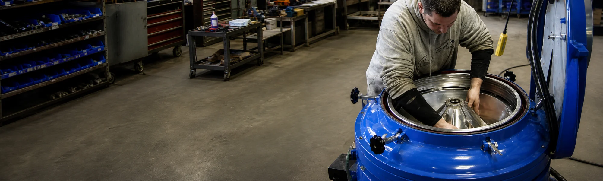
The featured image on the top of the page is an Alfa Laval disc stack centrifuge bowl cross-section showing the parts' location within the centrifuge bowl.
This list is alphabetically organized.
Disc Centrifuge Parts Glossary
Bowl Disc (aka disk, conical plate, plate-stack, disc-stack)
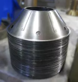
A bowl disc is a conical-shaped plate inside the rotating bowl assembly of the disc centrifuge. A stack of these discs is the heart of disc-type industrial centrifuges.
The purpose of these discs is to increase the surface area of settling available to the rotating fluids inside the bowl. This added surface area increases the efficiency of the centrifuge multi-fold. In other words, the discs reduce the settling distance of the process liquid. The photo shows a complete disc stack from an Alfa Laval centrifuge bowl.
The inter-disc spacing is maintained using caulks (or ribs), which are thin strips of steel welded to the discs' surface. These caulks are radially oriented and uniformly spaced around each bowl disc surface. The radial orientation of the caulks allows the flow of the process fluid in the same direction.
There are evenly spaced and matching holes on all the discs in a stack. These holes form a channel allowing upward movement of the process fluid through the disc stack. Depending on the centrifuge, these holes are closer to the outer periphery of the inner edge of the discs.
Another variation between discs is the caulk thickness, which varies the inter-disc spacing. For thicker or more viscous fluids, the caulks are thinner. This implies that the discs are closer to each other. The caulks are thicker for less viscous fluids (like water), allowing a wider gap between the discs.
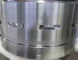
Bowl Body (aka Bowl Drum, Bowl Shell)
The bowl of a disc centrifuge is the outer, rotating body that houses all the bowl assembly components. Bowl bodies rotate upwards of 5000 RPM up to 15,000 RPM.
Depending on the type of centrifuge, the bowl body may have slots around the periphery in the 'self-cleaning' centrifuges. These slots or ports are openings for the sludge to exit the bowl during the sludge ejection process. These sludge discharge ports can wear out based on the type of solids, especially in the case of abrasive particles.
Manual clean centrifuges have a solids bowl body without any slots or ports.
Bowl Hood (aka Bowl Top)
The bowl hood is the upper cover on the centrifuge bowl body. Once assembled with the bowl body, this forms the complete outer envelope of the rotating bowl assembly. The bowl body is assembled on the upper end of the bowl spindle.
The large lock ring integrates the bowl hood into the bowl body.
Bowl Liner (aka Piston Liner)
The sliding piston is one of two moving parts within the bowl. This part is discussed in a subsequent section below. The process fluid flows along the upper surface of this part.
The bowl liner is a thin, steel part that is installed on top of the sliding piston within the disc centrifuge bowl. This liner protects the piston from wear, which can occur when the process fluid carries abrasive solids.
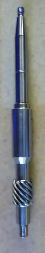
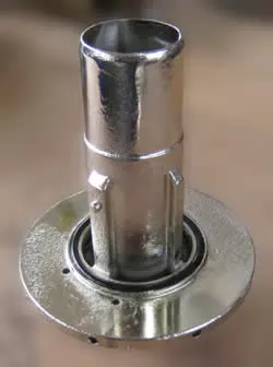
Bowl Spindle
The bowl spindle is the vertical transmission shaft of the disc centrifuge. It transmits the rotation from the gear train to the bowl assembly. The centrifuge bowl body is assembled on top of the bowl spindle.
The upper part of the bowl spindle has a precise taper section with a corresponding tapered hole in the bowl body. These tapers have to be precisely ground to match each other. Mating these two conical parts ensures complete surface contact between the bowl spindle and the bowl body. The friction between these components transmits the rotation from the spindle to the bowl assembly.
Therefore the bowl and spindle tapers need to match precisely for the smooth operation of the centrifuge. Any mismatch between the conical surfaces leads to the bowl mass being off-center from the rotating axis. At the operating speed of the bowl, this can cause imbalance and lead to excessive centrifuge vibrations.
Precision machined surfaces in the middle section of the bowl spindle for mounting the bearings.
The lower part of the bowl spindle has a worm gear mounted on it. In some smaller centrifuges, this gear is integral to the bowl spindle.
Bowl spindle runout is an essential checkpoint during disc centrifuge repair. Minor deviations in the spindle's straightness can occur over time, leading to a slight runout at the top of the shaft. The loss of concentricity leads to excessive centrifuge vibrations due to the rotating bowl mass being off-center.
Control Paring Disc
The control paring disc is part of the operating water system of 'self-cleaning' centrifuges. It is a non-rotating part that functions as a water-conveying device. It transfers water from the stationary frame of the centrifuge to the rotating bowl assembly.
In a fully assembled centrifuge, the control paring disc is stationary and positioned within the underside of the rotating bowl body. It discharges the water in the form of a jet that enters the open cavity inside the rotating distributing ring (explained below). This mechanism allows the transfer of the operating water between the stationary and rotating parts of the bowl.
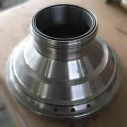
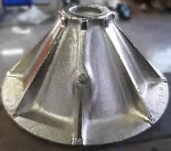
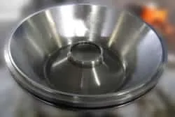
Distributing Cone
The distributing cone is part of the rotating bowl assembly. It is located within the bowl body above the sliding piston (described below).
The distributing cone distributes the incoming fluid smoothly within the underside of the distributor. The distributor is described in detail in the following section.
Distributing Cover
A distributing cover is another component of the operating water system attached to the centrifuge frame underneath the bowl body. The bowl spindle passes through the distributing cover. The control paring disc (detailed above) mounts on the distributing cover.
This component 'covers' the frame opening below it - that's why the 'cover' is in its name. It is a conduit for the operating water and carries the water to the control paring disc. There are intricate passages within the distributing cover for water to flow through.
The internal passages can get clogged with sludge and mineral deposits from the water over time. Keeping the distributing cover clean from the inside is critical to ensure the centrifuge's trouble-free operation.
This is a critical part of the operating water system of the centrifuge. The functional aspect of this part is explained in our Bowl Troubleshooting article.
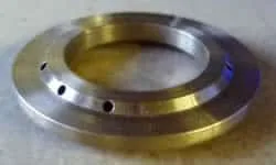
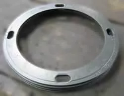
Distributing Ring (aka Water Ring)
The distributing ring is a rotating component that is a part of the centrifuge's operating water system. As referenced in the control paring disc section above, the distributing ring corresponds to the water transfer mechanism.
This part nestles within the bottom section of the rotating bowl body. It is fastened to the bowl body by bolts from within the bowl.
The jet of water from the control paring disc enters a precisely located opening on the inner diameter of the distributing ring. The centrifugal force radiates this water outwards into the water passage within the bowl body.
This is also a critical part of the operating water system of the centrifuge. The functional aspect of this part is explained in our Bowl Troubleshooting article.
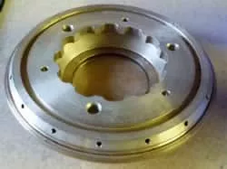
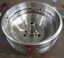
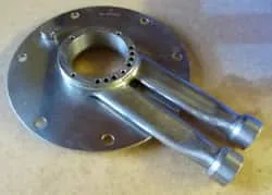
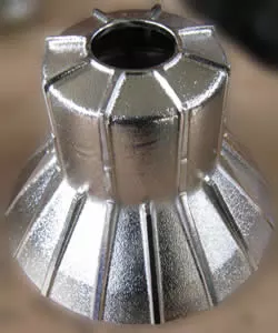
Distributor (aka Disc Carrier, Disc Tower)
As the alternate name 'disc carrier' implies, the centrifuge distributor has mounted all the discs (stack). The distributor is the fixture for the conical plates within the centrifuge bowl. It aligns the cones correctly using an alignment key and corresponding slots on all discs.
The process fluid flows through the center of the distributor towards the distributing cone below it. The distributor has holes that line up with the holes in the discs. The process fluid passes through these holes into the disc stack.
The distributor features radial ribs around its core, which creates a gap between the discs' inner edge and the center of the distributor. The separated liquid flows through this gap upwards towards the bowl top.
The alignment key embedded in the distributor is a critical component. The distributor wears due to the constant flow of fluid with sludge along its surface. This wear can cause the discs to fit loosely around the ribs of the distributor.
Excessive wear can allow the discs to rotate about the distributor. This misalignment causes the holes on the distributor to not line up with those in the discs. The fluids can no longer flow in the designed passages leading to the malfunction of the centrifuge.
Gravity Disc (aka Gravity Ring)
The gravity disc is a stamped steel part on top of the disc centrifuge bowl hood. The gravity disc has a controlled inside diameter hole, which controls the position of the interface between the two liquid phases in the case of a liquid-liquid separation centrifuge.
This interface is critical for the operation of the centrifuge. If the interface is too far radially outward (large gravity ring hole size), there is not enough heavy phase liquid in the bowl.
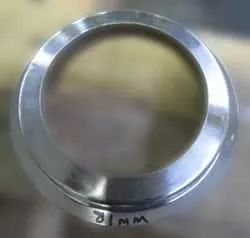
The inner oil column's hydrostatic pressure pushes out the water phase and exits the bowl through the heavy phase outlet. This condition is undesirable, as the lighter fluid (usual oil) is now exiting the bowl through the incorrect outlet. This is the 'break-over' condition discussed further down in this article.
A nomogram helps the operator select the correct gravity disc size for the process fluids. It uses the ratio of the specific gravities of the two liquids, the throughput volume, and process fluid temperature to determine the right gravity disc. Each Alfa Laval disc centrifuge model has a corresponding nomogram chart to go with it.
Large Lock Ring
As the name suggests, this is a steel ring that locks the bowl hood to the bowl body. This ring has external threads with matching female threads in the bowl body.
The purpose of this ring is to compress the bowl hood to the bowl body. The compression of the bowl hood also compresses the other parts inside the rotating bowl assembly. This tightening squeezes all the bowl parts together, forming a rigid and integral bowl assembly.
One key aspect of this process is repeatedly impacting the lock ring tightening tool. The OEM recommends a heavy sledgehammer for this locking action. The lock ring and the bowl body have respective marks that need to be aligned to ensure complete tightening of the bowl.
Nylon Seal Ring (aka Bowl Seal Ring)
The sliding piston lip (described below) and the nylon seal ring form the primary seal in the self-cleaning centrifuge bowl. This seal ring fits into a groove in the bowl hood. Its location matches the location of the lip on the sliding piston.
The nylon seal ring is a consumable part. It is essential to periodically replace this part to prevent wear on the bowl's sliding piston (non-replaceable part). For more information, read our disc centrifuge bowl leak troubleshooting article.
During regular use of the centrifuge, the operator should regularly inspect the nylon seal ring to check for excess wear on the sealing surface.

Operating Slide
The operating slide is the lowermost part of the rotating bowl assembly. This part is the other moving component within the bowl.
The movement of the operating slide opens and closes the water chamber below the sliding piston. The ingress and egress of water from and to this chamber cause the vertical movement of the piston. This movement of the piston triggers the sludge ejection cycle.
The sliding does not come in contact with the process fluid. Therefore, this component does not experience process fluid-related wear or corrosion.
However, the operating slide is always immersed in the operating water. Salt water or hard water can corrode the operating slide over prolonged exposure. Mineral deposits from hard water can impede the operation of this slide, causing centrifuge operational issues.
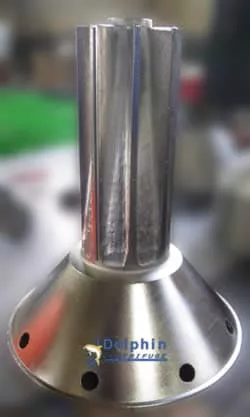
Paring Disc (aka Paring Disc Pump, Centripetal Pump)
The paring disc is a static impeller device that is internal to the bowl. Though this part is inside the bowl assembly, it does not rotate. It is suspended inside the upper chamber of the bowl, which revolves around it.
The paring disc is a centripetal pump, which converts the fluid's rotational energy inside the bowl into pressure. It performs this pumping action through internal spiral vanes.
This pump is threaded on the feed tube and connects to the upper fluid discharge assemblies.
The bowl cavity housing the paring disc has a tight tolerance. This close gap means that properly assembling these components is critical because the other parts close to the paring disc are rotating.
Any contact between this stationary part and the rotating parts can cause catastrophic damage to the centrifuge.
Port Liner (aka Port Wear Clips)
|
The exposure of the sludge ejection ports in the bowl body to wear is a cause for concern. Port liners are stamped steel clips that are crimped over the exposed sludge ports. They protect the centrifuge bowl body ports from wear. The port liner is a sacrificial part that is easily replaced at a minimal cost. | 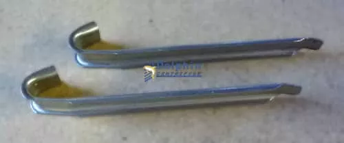 |
Sliding Piston (aka Sliding Bowl Bottom)
A brief introduction of the sliding piston is in the 'bowl liner' section above. This part is also known as the sliding bowl bottom because it slides downward at the bottom of the fluid chamber. The evacuation of the water below the piston causes the piston's downward movement.
This sliding motion of the piston opens the sludge discharge ports to the bowl's interior. The high centrifugal force exerted within the bowl pushes the accumulated solids instantly through these exposed ports. This action comprises the sludge ejection cycle of the self-cleaning centrifuge.
The sliding piston has another essential feature designed into it. A small circumferential protrusion, known as a lip, is machined onto the sliding piston's upper surface. This lip embeds into a mating part inserted into the bowl hood to form a seal. This seal keeps the bowl contents from exiting the bowl under the high centrifugal forces during regular operation.
It is essential to mention that erosion of the above-mentioned sliding-piston lip can cause the bowl contents to leak during operation. This leak can cause the separated solids to exit the bowl at a high velocity causing more wear on the lip. Therefore it is crucial to replace the nylon seal ring (explained above) to prevent wear of the sliding piston, which can be an expensive replacement.
Detailed information about Bowl Leaking and prevention is on our recent disc-centrifuge troubleshooting guide.
Sludge Ports (aka Sludge Ejection Ports)
Sludge ports are rectangular slots machined on the disc centrifuge bowl body. As described in the port liner section above, these openings allow the separated solids to exit the bowl during the solids' ejection process.
Again, it is essential to protect these ports from wear by using port liners in abrasive sludge applications.
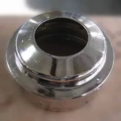
Small Lock Ring (aka Paring Chamber Cover)
The small lock ring is an internally threaded part that screws onto the top of the bowl hood. It secures the gravity disc to the bowl hood and houses a chamber for the heavy phase's paring disc pump.
Top Disc
The top disc is a dome-shaped part positioned at the top of the disc stack. It acts as a collection cover, which funnels the separated light phase towards the center of the bowl top. The light-phase paring disc (stationary) is housed within the top disc and pumps out this clean light phase.
The separated heavy phase travels over the upper surface of the top disc and enters the small lock ring chamber. In certain respects, the top disc also acts as a barrier between the two separated phases of liquids.
Top discs can experience some wear if the process fluid carries abrasive particles.
Request Parts Quote
Send us your list of disc centrifuge parts. We respond within 1 to 2 business days with availability and pricing.
Unique Terms Specific to Disc Centrifuges
Specific terms are unique to the world of disc centrifuges. These terms are rare in the context of other machinery or separation equipment. In this section, we will explain some of these terms and their relevance to aspects of disc centrifuges.
| Unique Term | Alternate Term(s) | Disc Centrifuge Relevance |
|---|---|---|
| Back-Pressure | As discussed in the 'paring disc' section above, the liquid phases are pumped out under pressure from the centrifuge bowl through a paring disc pump. Throttling the liquid outlet exerts back pressure on the exiting fluid stream. Back-pressure on the liquid outlet ensures that the paring disc impeller is immersed in the clean separated fluid. Therefore, back-pressure is only applicable to pumped fluid outlets with paring discs. Also, applying back pressure on the liquid effluent causes pressure on the fluid column within the centrifuge bowl. This pressure, in turn, has a beneficial effect on the centrifuge operation. It helps stabilize the liquid columns within the bowl, which leads to a stable interface between the liquid phases. Thus, back pressure results in better separation of the liquid phases. | |
| Bowl Closing | This term is specific to 'self-cleaning' centrifuges. In this case, the centrifuge bowl requires water to push the operating slide and, subsequently, the sliding piston to form the seal. This event of the piston moving within the bowl to form the seal is known as bowl closing. | |
| Bowl Opening | Bowl Shoot, Sludge Dump | Bowl opening is the momentary event where the sliding piston is activated to move downward, exposing the sludge ejection ports. The high centrifugal forces cause the sludge to exit the bowl in a short period. This event is often triggered by a pulse of high-pressure water in the operating water system. |
| Break Over | Liquid Seal Break | Break over refers to the phenomenon where the lighter fluid (liquid/liquid separation) escapes the centrifuge bowl through the passage designed for the heavy fluid. Liquid seal breaks can occur due to multiple causes. It could be caused by the bowl not being primed before the lighter fluid flows into the bowl. In the absence of the heavy liquid, the lighter fluid exits the bowl through the passage designed for the heavier fluid. It could also happen if the gravity disc installed in the centrifuge is too large. In this case, the heavy liquid column within the bowl does not have adequate hydrostatic pressure to balance the lighter fluid pressure. The lighter fluid can push out the heavier fluid and escape through the path designed for the heavy liquid. |
| Clarifier Centrifuge | Liquid/Solid Centrifuge | A clarifier is a disc centrifuge configured to separate one liquid phase from solids. In other words, a two-phase centrifuge. An example of a clarifier centrifuge would be one set up to separate the beer from yeast. |
| Concentrator Centrifuge | Liquid/Liquid/Solid Centrifuge | A three-phase centrifuge is designed to separate two liquids and solids simultaneously. However, a centrifuge specifically designed for a larger proportion of the heavy liquid than the lighter liquid is a concentrator. A machining coolant centrifuge is an example of a concentrator centrifuge. It is designed to separate small amounts of tramp oil (light phase) from large volumes of coolant (water). |
| Displacement Water | In simple terms, displacement water is supplied to the centrifuge bowl before the sludge shoot cycle. The purpose of the displacement water is to replace the oil in the centrifuge bowl to reduce oil losses during the sludge discharge. | |
| Drain Time | During the bowl open (shoot) part of the process, the centrifuge operating water system is flooded with water in the chamber above the operating slide. The drain time is between the opening and closing sequences to allow this opening water to escape the bowl. This is to ensure that the closing operation of the bowl is accomplished smoothly. | |
| Heavy Phase | The heavy phase refers to the liquid with the higher specific gravity in the mix of liquids separated by the centrifuge. In the case of oil and water, water is the heavy phase. This term is only applicable to the separation of two liquids. | |
| Light Phase | Following the above, the light phase is the liquid with the lower specific gravity in the mix of liquids being separated. In the case of oil and water, oil is the light phase. This term is also only applicable to the separation of two liquids. | |
| Liquid-Liquid Interface | During the separation of two liquids, the liquids form concentric columns within the bowl. The liquid-liquid interface is the boundary between these liquids within the bowl. | |
| Liquid Seal | Bowl Prime, Priming Liquid | The liquid seal refers to introducing the heavier phase into the centrifuge bowl before the process liquid. The centrifuge bowl's design requires the heavy phase space within the bowl to be filled before the light phase enters the bowl. This prevents the light phase from exiting the bowl through the heavy phase pathway. A liquid seal is needed only in liquid/liquid separation cases wherein the lighter phase is the predominant liquid phase. |
| Operating Water | Closing Water, Opening Water | A self-cleaning centrifuge bowl ejects the separated solids by operating the sliding piston through a hydraulic mechanism. The operating water is the term for the water used for this operation. |
| Purifier Centrifuge | As explained above, a three-phase centrifuge separates two liquids and solids simultaneously. However, a centrifuge specifically designed for a smaller proportion of the heavy liquid than the lighter liquid is a purifier. A diesel fuel centrifuge is an example of a purifier centrifuge. It is designed to separate small amounts of water (heavy phase) from large diesel volumes. |
Summary
We hope this glossary of disc centrifuge terms helps the new or existing users of industrial disc centrifuges. Though the terms referenced in this article are specific to Alfa Laval Disc Centrifuges, they are similar to those used for other disc centrifuges manufactured by GEA Westfalia.
Feel free to contact Dolphin Centrifuge if you have questions or need some application consulting. You can also reach us by calling (248) 522-2573.